
Post author:
Kristel Sapungan
Construction drawings show how a building will be built using plans, symbols, and technical details. This guide covers drawing types, software, reading tips, and coordination tools.
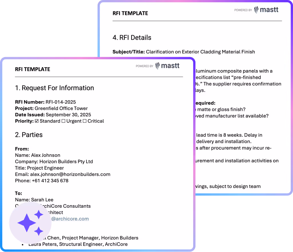
Use this construction RFI template to submit design clarifications and contractor questions with clarity. Ensure every request for information is properly documented, answered, and tracked in one structured format.

Construction drawings and documents guide every phase of a construction project from concept through completion. They show contractors exactly what to build, with what materials, and how to meet code and safety requirements.
This article explains how these drawings are developed, issued, and used in the field, and outlines the types you’ll encounter most.
Construction drawings are technical documents that show, in detail, how something will be built. They are precise, scaled drawings used in construction projects to visually communicate the size, shape, layout, and materials of a building or structure.
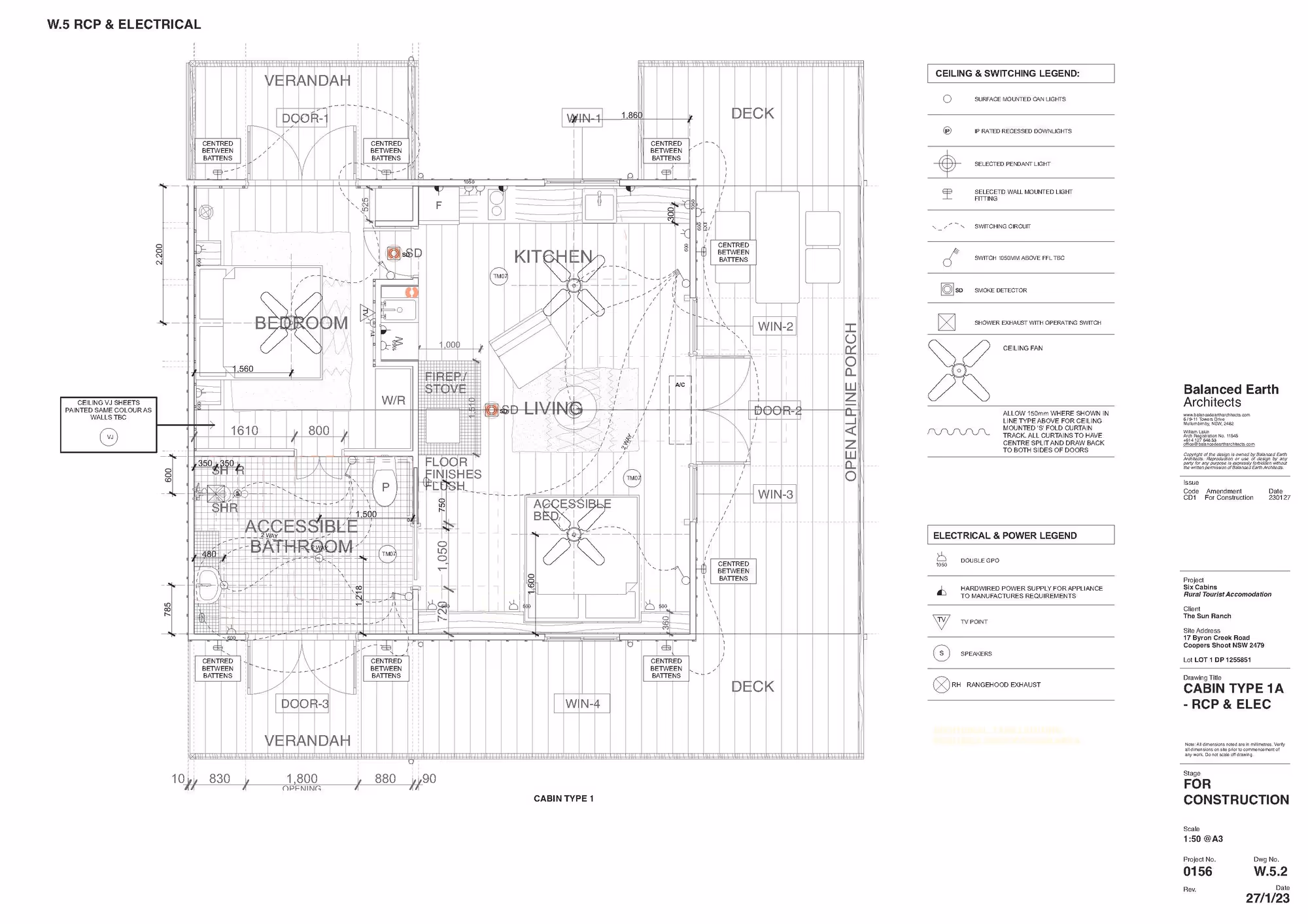
These drawings include floor plans, elevation drawings, section drawings, and other views that explain how different parts fit together. Each construction drawing uses standardized symbols, dimensions, and notes to remove guesswork and ensure that every part of the design is clearly understood.
Created by architects, engineers, or designers, construction drawings form part of the official construction documents used throughout the 4 phases of construction.

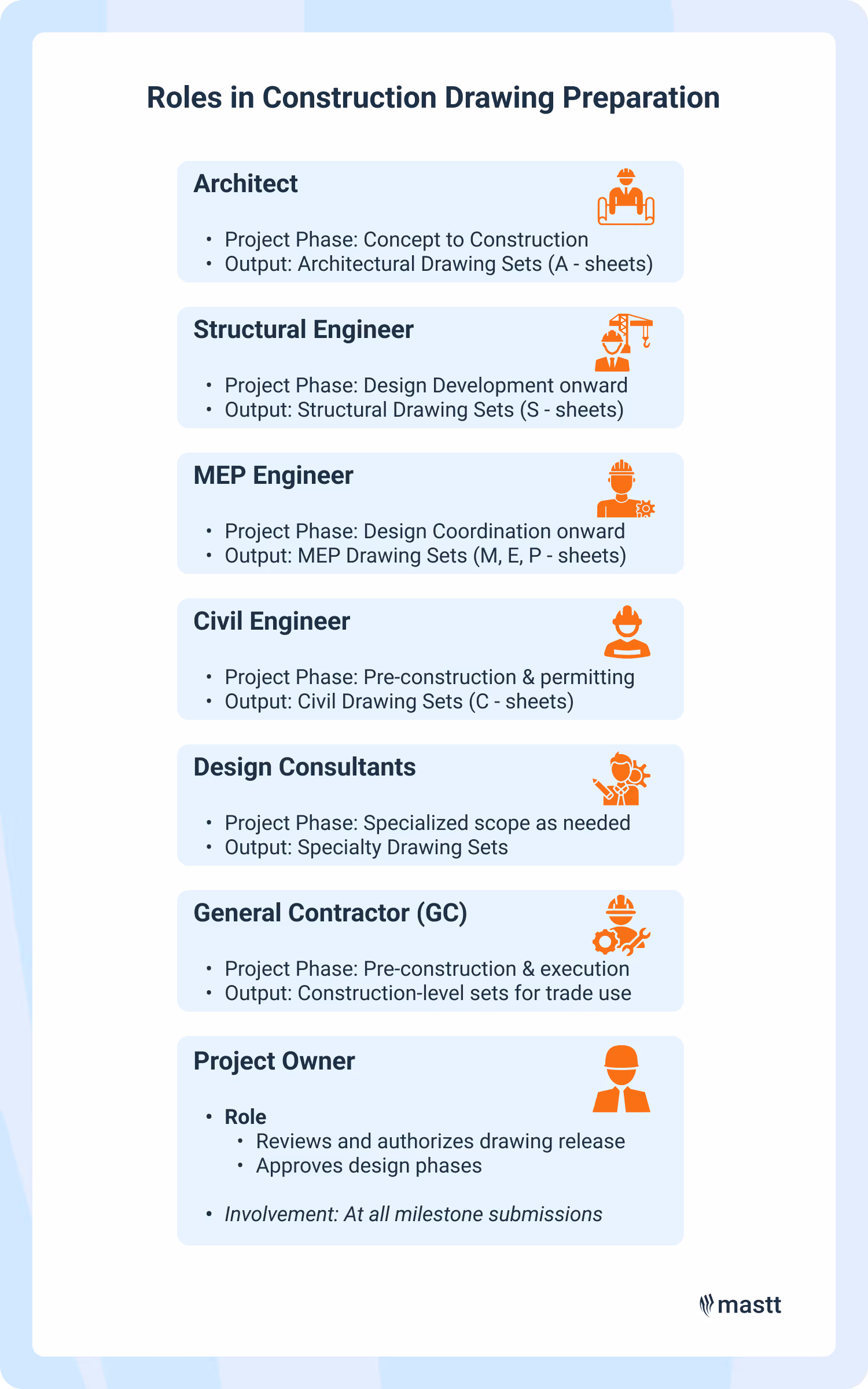
Construction drawings are prepared by licensed professionals, typically architects, engineers, and design consultants who are responsible for creating accurate, code-compliant plans. These drawings are then issued to general contractors, subcontractors, and permitting authorities for use during design review, construction, and inspections.
Construction drawings rely on a coordinated, multidisciplinary effort. The key roles in preparing and issuing construction drawings are:
Construction drawings are issued in defined stages. They usually begin as design development sets, then progress to construction documentation, and end as record drawings. You can start calling them construction drawings once the plans are detailed enough for site use.
Each construction document is marked for its intended use (e.g. "For Review," "For Construction"). Once finalized, they are stamped, signed, and distributed through digital drawing management platforms or official submittal channels.
Construction drawings contain precise technical information that guides every phase of a project, from permitting to building. Each technical drawing outlines the size, location, materials, and relationships between components using standardized symbols, notes, and dimensions.
Here's the typical information found in construction drawings:
Construction documents may also include phasing instructions, coordination marks, or keynotes that support sequencing and site management. For example, a floor plan might call out a specific wall type that cross-references a detailed assembly drawing on another sheet. This layered structure helps keep every separate drawing connected and traceable.
Construction drawings are organized by purpose. Each category focuses on specific information like site layout, architectural form, structure, systems, or fabrication. Contractors use them in sequence, layer by layer, to build exactly what was designed.

As-built and record drawings both track project changes, but they’re created by different parties and serve different ends. As-builts document what was built in the field; record drawings formalize that data into final, verified documents for turnover.
Reading construction drawings starts with knowing where to look. Focus on the title block, drawing scale, and layout first, then move through the sheet using legends, notes, and callouts to interpret what’s being built and how.
To understand them fully, you’ll need to recognize standard symbols, follow cross-references, and practice working across multiple drawing types. Whether you're reviewing an electrical drawing, plumbing drawing, or architectural drawing, the fundamentals remain consistent.
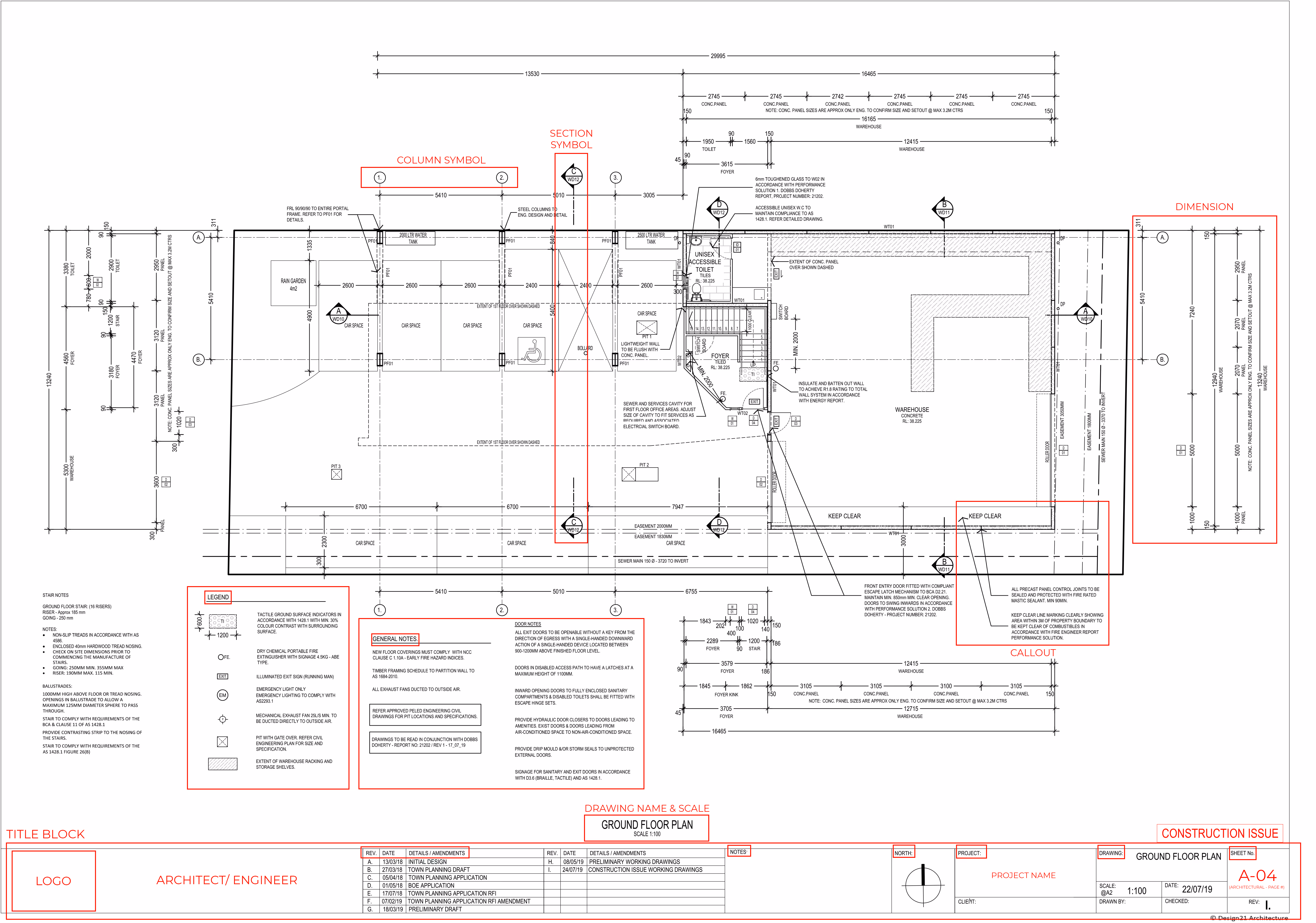
Begin by checking the title block, drawing index, and scale to understand the sheet’s purpose and how to read it. This helps you identify what kind of drawing you're looking at, how it's organized, and how measurements apply.
Focus on the legend, line types, grid lines, and callouts to interpret details quickly. These elements help you navigate sheets and locate specific components or views in structural drawings, mechanical drawings, or section drawings.
Use notes, directional markers, and cross-referencing across sheets to piece together the full design intent. This ensures consistency between architectural, MEP, and structural plans on any construction project.
Study real-world construction drawings, visit sites, and use reference guides to deepen your knowledge. These practices reinforce your ability to read working drawings accurately under real project conditions.
With regular practice and the right references, reading construction drawings becomes second nature. You'll become a more confident, efficient, and proactive contributor to any construction team.
Construction drawing sets are issued at different stages to meet specific needs. Permit sets go to building departments for code review, working sets support coordination and bidding, and construction sets guide actual building in the field. Each type contributes to the broader set of construction documents and the construction process itself.
Each drawing set evolves in complexity and detail. Permit sets focus on compliance, while construction sets include every detail needed for installation, fabrication, and inspections. For example, a construction set will show not just wall locations but also reinforcement, anchor points, component drawings, and finish specs needed to build exactly what's approved.
Construction drawings often cause problems when they’re unclear, outdated, or poorly managed. These issues lead to miscommunication, schedule delays, and costly rework. Key pain points stem from missing revisions, inconsistent formatting, versioning issues, and coordination breakdowns across disciplines in construction projects.
Trade conflicts happen when sheets aren’t aligned across disciplines. These issues delay field work and lead to RFIs or costly rework.
🧩 Solution: Coordinate across disciplines and adopt drawing management software that supports model integration.
Formatting inconsistencies slow down interpretation and confuse field teams. Different symbols and notes across sheets reduce efficiency.
🧾 Solution: Limit manual edits and enforce standardized formatting through digital workflows and drawing templates.
When revisions are missed, crews rely on outdated plans, risking safety and compliance. Critical design changes can be overlooked.
🕵️ Solution: Track all revisions, highlight them with revision clouds and tags, and maintain a detailed change log.
Crews may build from obsolete drawings, resulting in errors that require rework. This wastes time, labor, and materials.
📤 Solution: Control access digitally and issue drawings by version to ensure teams are always using the most current set.
Without version control, multiple drawing sets circulate with no clarity on which is current. This leads to miscommunication and mistakes.
📁 Solution: Stamp final sets, issue drawings by version, and restrict access to unapproved files.
Crews using printed or offline drawings might rely on outdated information. This raises the chance of installation errors.
☁️ Solution: Provide real-time access through cloud-based platforms with offline capability and permission control.
Missing dimensions or vague callouts cause confusion and slow down construction. Workers must stop to clarify details.
📐 Solution: Adopt drawing management software and include clear notes, legends, and linked detail references on each sheet.
When drawings are late, work can’t move forward. Delays in procurement, inspections, and field activity often follow.
⏱️ Solution: Distribute updates promptly and maintain internal workflows for drawing delivery deadlines.
Too many RFIs slow down design and construction coordination. Unclear drawings create unnecessary back-and-forth.
📌 Solution: Use revision clouds and tags to make changes visible, and maintain a change log to reduce back-and-forth.
Improper storage of drawings leads to missing revisions and unresolved disputes. Teams lose access to project history.
🗃️ Solution: Archive superseded sets and enable audit trails to create a traceable, searchable record of every issued drawing.

Construction drawing software is a digital solution that allows teams to create, view, manage, and share construction documents in real time. These tools combine CAD drafting, document control system, and cloud collaboration to reduce errors, speed up communication, and streamline coordination from design through to handover.
All these are essential for managing technical drawings and improving accuracy across all types of drawings, from shop drawings to HVAC drawings and plumbing drawings.
These platforms support the full lifecycle of construction documentation from schematic design to coordinated IFC drawing sets. When integrated well, these tools help eliminate delays, reduce RFIs, and improve drawing accuracy across the board. They're particularly useful for managing working drawings, finishing drawings, elevation drawings, and record drawings.

Construction drawings are the backbone of cost control, schedule certainty, and code compliance. They reduce risk, prevent rework, and protect your investment.
Prioritize drawing quality early to set your project up for success. From building design and interior design to site plan drawings and presentation drawings, these documents guide every phase of a construction project and empower the entire design team, contractor, and construction team to execute accurately and efficiently.
Written by
Kristel Sapungan is a licensed architect and Content Writer at Mastt, combining her technical background with expertise in SEO and digital strategy. With experience in architectural design, construction documentation, and on-site coordination, she delivers precise, high-quality content for the construction and capital works sector. Her work enhances industry communication by translating complex concepts into clear, professional narratives.


Contributions from

Cut the stress of showing up unprepared
Start for FreeTrusted by the bold, the brave, and the brilliant to deliver the future
