



.avif)

Not every AI tool can read construction drawings accurately, especially when working with large PDF sets. Symbols, notes, and references across multiple sheets can lead to missing details or unreliable answers.
This guide shows how to use Claude Code to preprocess drawing sets into searchable files before querying them. It also covers Airtable and NotebookLM as alternative setups.
Step 1: Create a Project Folder for the Drawing Set
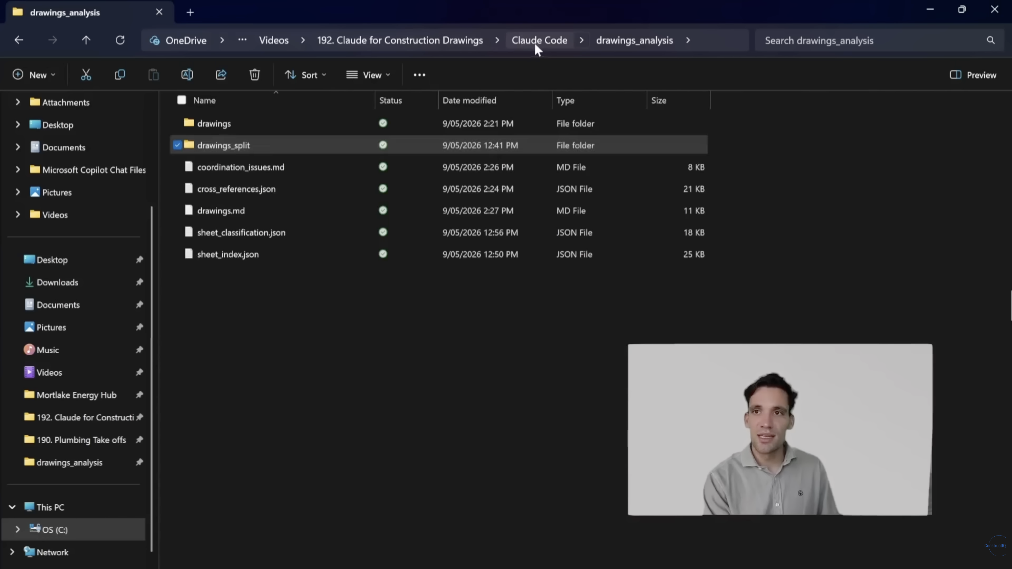
Create a dedicated local folder and place the complete PDF drawing set inside it. This folder becomes the workspace where Claude Code reads the source files and saves the processed drawing data.
Open Claude Code from the same folder. This gives it access to the merged PDF and allows it to run the scripts needed for preprocessing. The workflow can then split the package without repeatedly uploading the full file through Claude Chat or Cowork. See our guide to using Claude Cowork for construction for other project administration workflows.
Keep the original PDF in the folder as the source record. During preprocessing, Claude Code will create separate drawing sheets, rendered images, and text representations. It will also generate the indexes used to search the package.
The folder should eventually contain:
- The original merged PDF drawing set
- An individual PDF and image for each sheet
- Extracted text and available vector data
- A drawing register and sheet classification index
- A symbol library and cross-reference map
- Structured files for construction objects, notes, and specifications
At this stage, the aim is to give Claude Code one controlled location for the source drawings and every file created from them. Do not ask it to analyze the complete PDF yet. The following steps build the searchable structure first.
Step 2: Create the Drawing Analyzer Skill
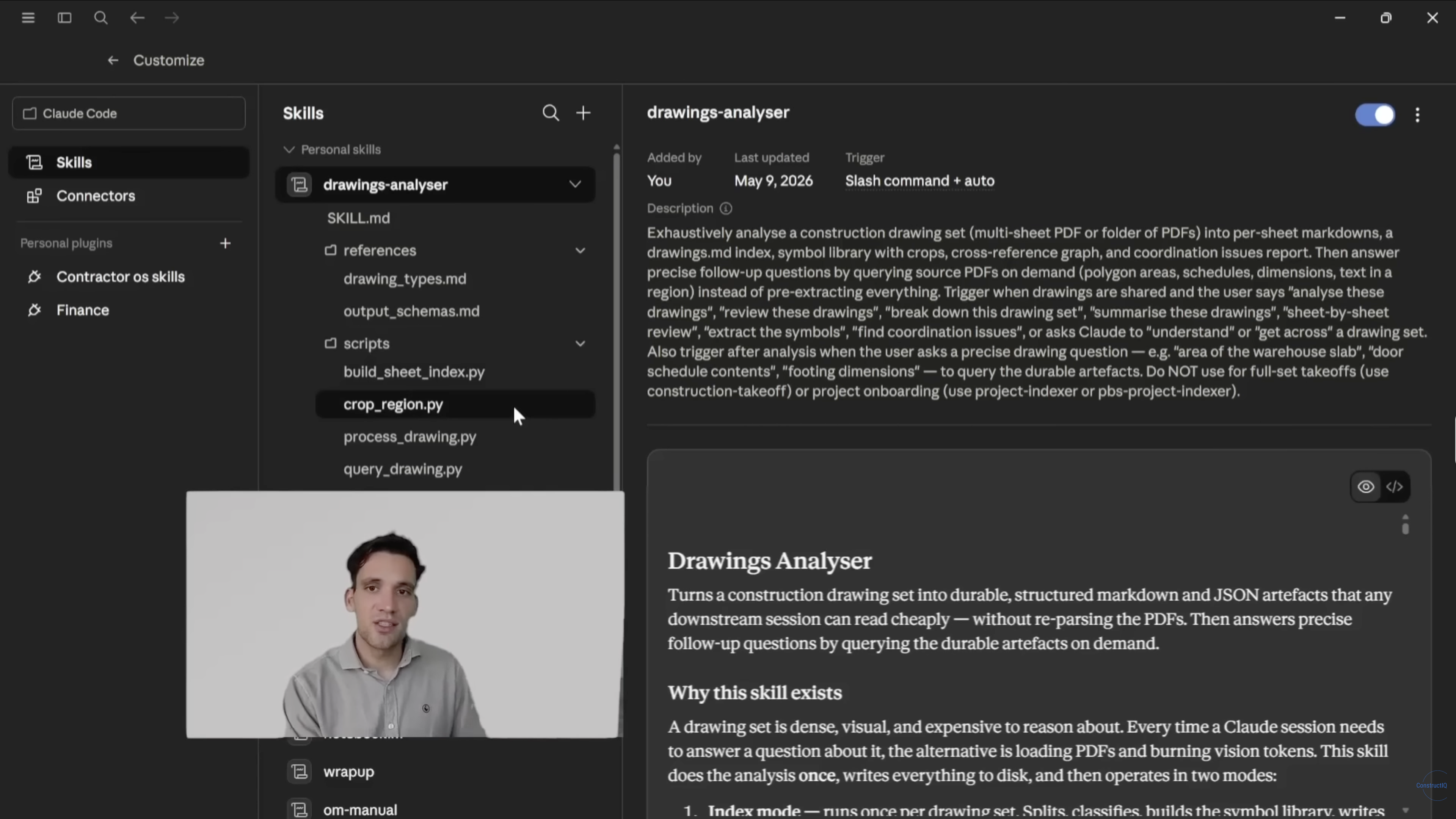
Create a reusable Claude skill that defines how Claude Code should process and query a set of construction drawings. Packaging the workflow as a skill lets you reuse the same instructions and output structure for each drawing package.
The drawing analyzer should separate mechanical file processing from drawing interpretation. Use Python scripts for repeatable tasks such as splitting PDFs, cropping sheets, rendering images, and extracting vector data. Let Claude classify the drawings and interpret their contents.
Build the following components into the skill:
- Processing scripts: Split the merged PDF and create an individual PDF, image, and text representation for each drawing.
drawings.md: Create an overall summary of the package and record what appears on each drawing. Include instructions for querying the processed files and returning to the relevant PDF.- Sheet classification matrix: List each drawing, determine its type, and record the main information shown.
- Cross-reference map: Record how plans connect to sections, details, schedules, and other referenced drawings.
- Symbol library: Extract the legends and symbols used across the drawing package.
- Object database: Group physical elements such as slabs, footings, pipe runs, and cable runs by object.
- Project wiki: Organize general notes, specifications, and other written requirements by topic.
- Query rules: Tell Claude to read the summary and structured data before opening an image or PDF.
- Source and confidence fields: Record the source drawing and reliability of each extracted value.
Avoid using fixed pattern-matching scripts to classify the drawings. Drawing titles and formats vary, so a rule based on one keyword may assign the wrong type. Claude should consider the title block, drawing layout, and information shown on the sheet.
Once the workflow, scripts, and output formats are in place, package them as the drawing analyzer skill. The next steps use that skill to process the PDF set in the project folder.
Step 3: Run the Drawing Analyzer Workflow
With the drawing analyzer skill ready, ask Claude Code to run it against the merged PDF in the project folder. Try this prompt:
Can you please run my drawing analyzer workflow on this set of construction drawings?
Claude Code will call the instructions and scripts stored inside the skill, then process each drawing in the package. This initial run splits the merged PDF and prepares the structured files used throughout the workflow.
Processing the full package uses more tokens than a later drawing query because Claude must build the searchable structure first. The analyzer only needs to complete this process once for each drawing set.
After the run finishes, Claude can search the drawing summary and structured data before opening the original PDF. Check that the required files were created before asking questions about the drawings.

Step 4: Check the Individual Drawing Files
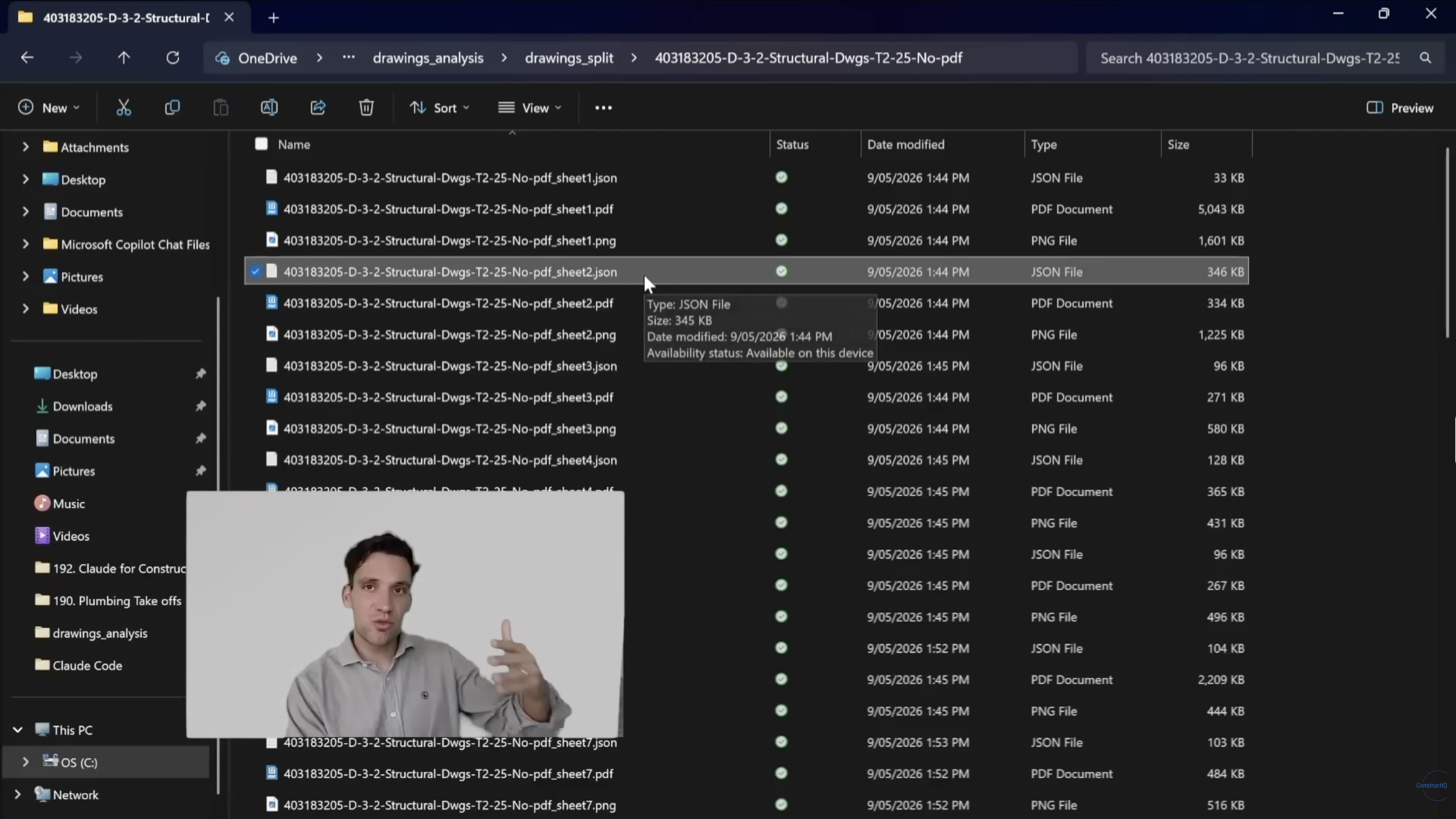
Once the drawing analyzer finishes, open the project folder and review the files it created. The merged package should now be separated into individual PDFs. Each drawing should also have a rendered image and text representation.
Each format gives Claude a different way to read the same drawing:
Claude starts with the text representation to identify the information on the drawing. If the question requires visual detail, it can inspect the rendered image before returning to the individual PDF.
The workflow can also extract embedded text with its position and orientation when the PDF contains vector data. Raster PDFs do not contain this layer, so Claude has less searchable information and must rely more heavily on the image.
Step 5: Review the Drawing Register and Classification Index
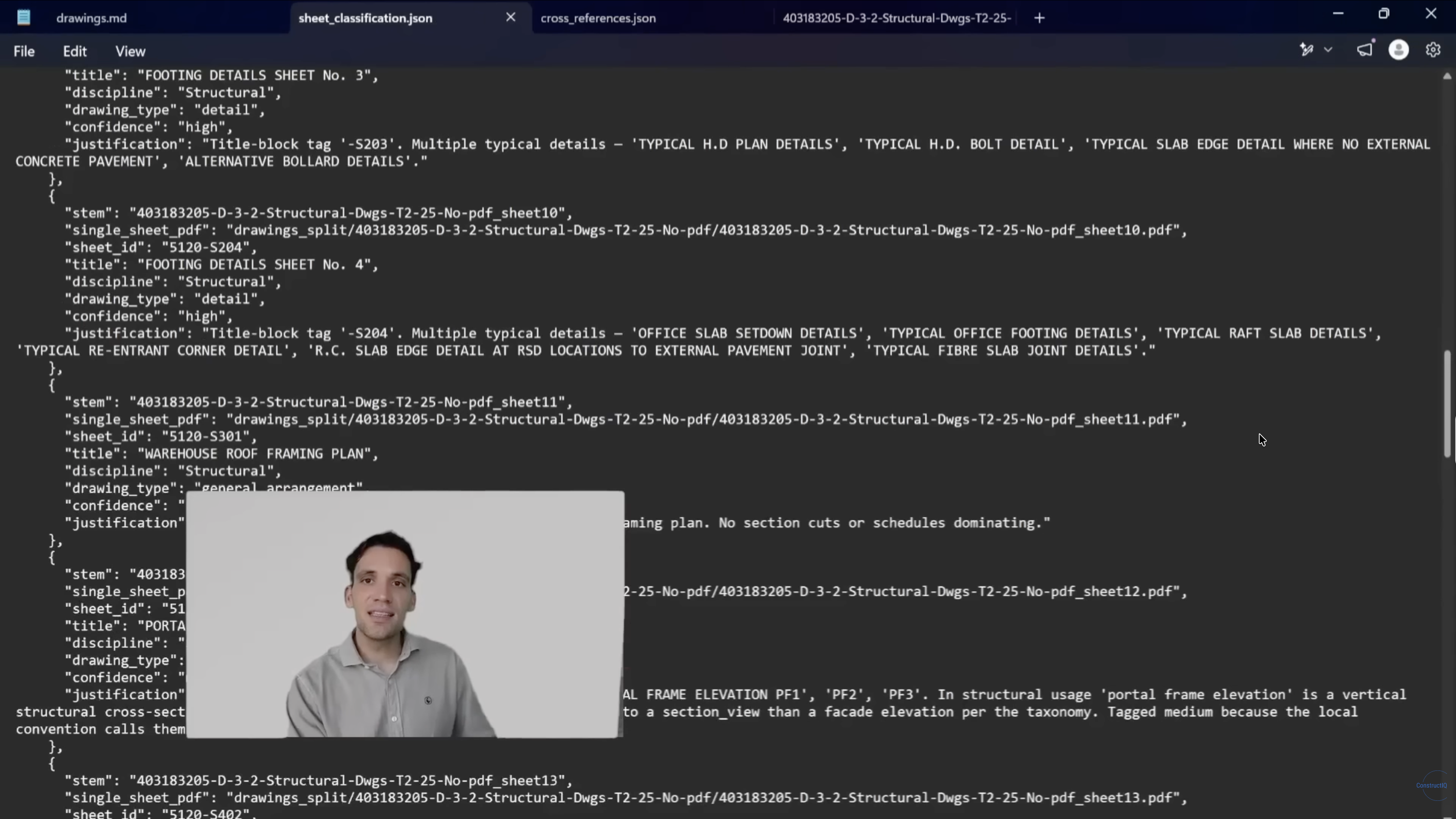
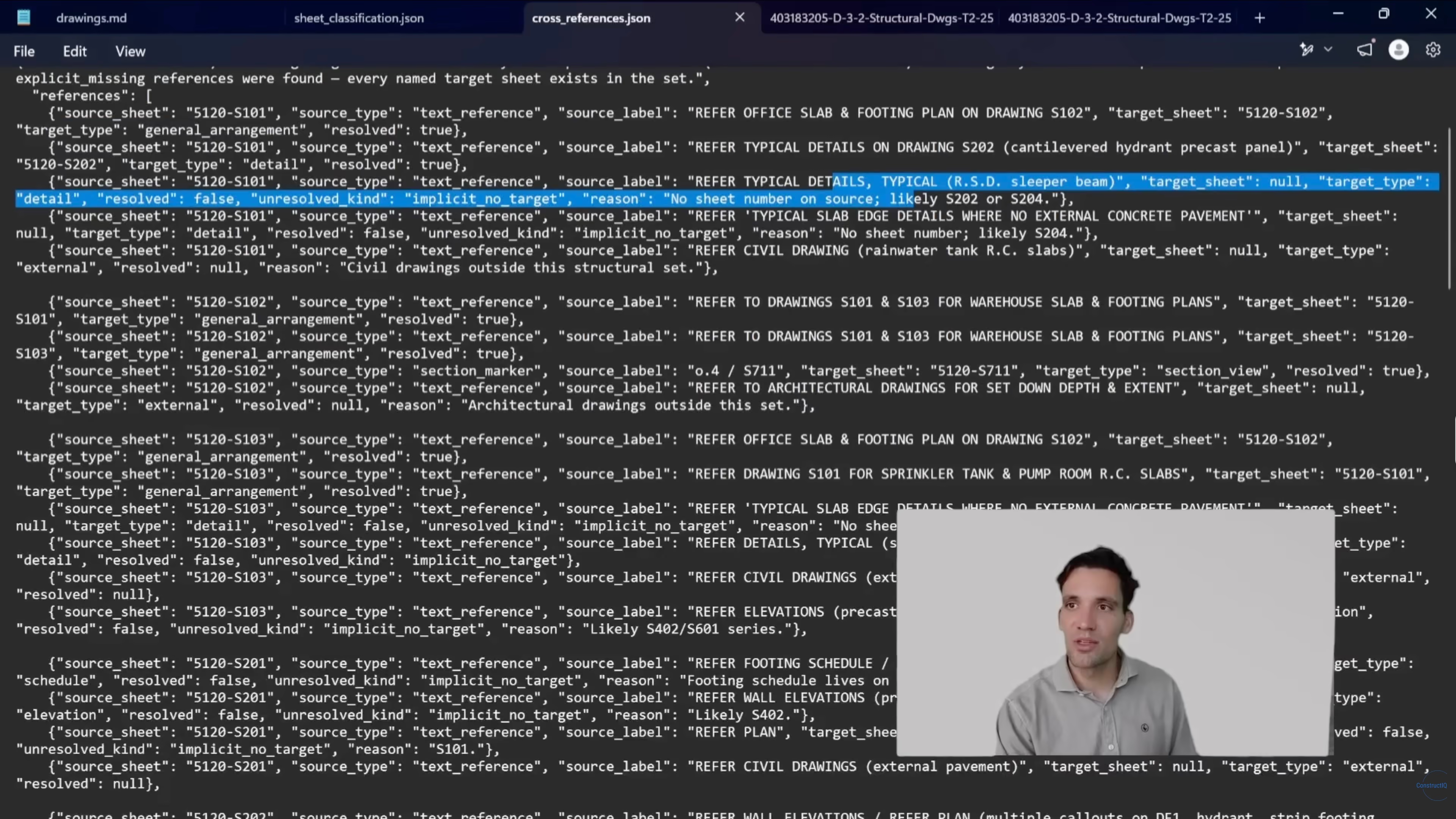
Once the analyzer finishes, open the drawings.md file and sheet classification matrix created during processing. These files give Claude a high-level map of the drawing package before it reads any individual sheet.
The drawings.md file should contain an overall summary of the package and describe what appears on each drawing. It should also explain how Claude should query the processed data and when it should return to the relevant PDF.
The sheet classification matrix gives Claude a more structured view of the package. It lists each drawing, identifies its type, and records the main information shown. The matrix can distinguish layouts, sections, schedules, details, and general notes.
Review both files before asking Claude questions about the drawings. Claude can load these small text files at the start of each query. This gives it enough context to locate the relevant drawing without processing the complete PDF package again.
Step 6: Check the Symbol and Cross-Reference Indexes
Also check the symbol library and cross-reference library created by the drawing analyzer. These files help Claude interpret drawing symbols and follow information across different sheets.
- Symbol library: Extracts symbols and legends from the drawing set. It stores them in a text file that Claude can search without reviewing every sheet again.
- Cross-reference library: Records what appears on each drawing and identifies the other drawings it refers to. This helps Claude understand how the complete drawing set fits together.
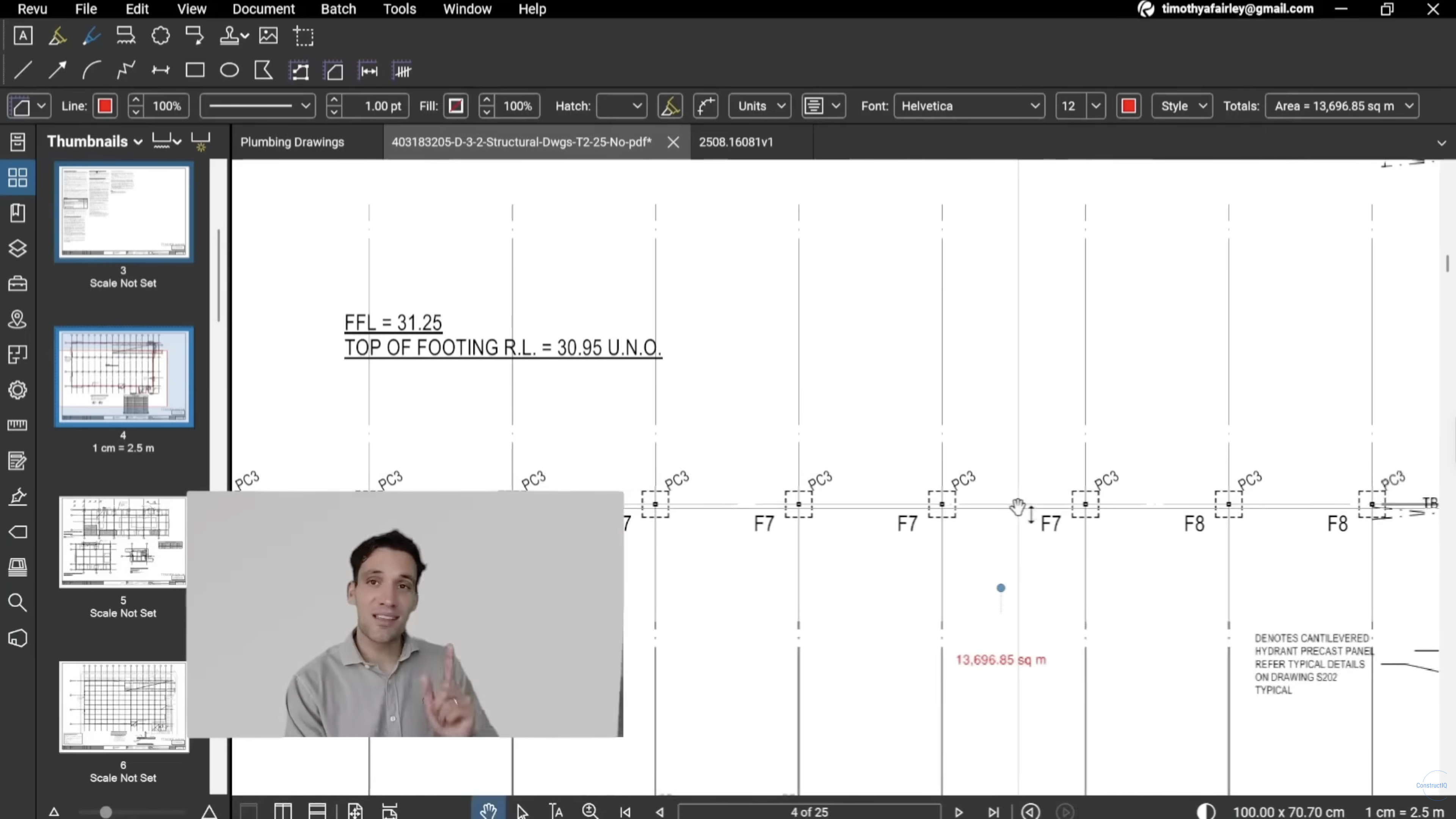
For example, an F6 footing tag on a layout does not show the footing’s full size. Claude must follow the reference to the relevant section drawing to find its depth and dimensions.
Check that the symbol library contains the extracted legends. Then confirm that the cross-reference library describes each drawing and links it to the correct related sheets. Missing entries could prevent Claude from finding the information needed for a later query.
Step 7: Review the Structured Drawing Database
Open the structured drawing database and project wiki created by the analyzer. Check how construction objects, written requirements, sources, and reliability ratings have been organized.
Review the files with the following checks:
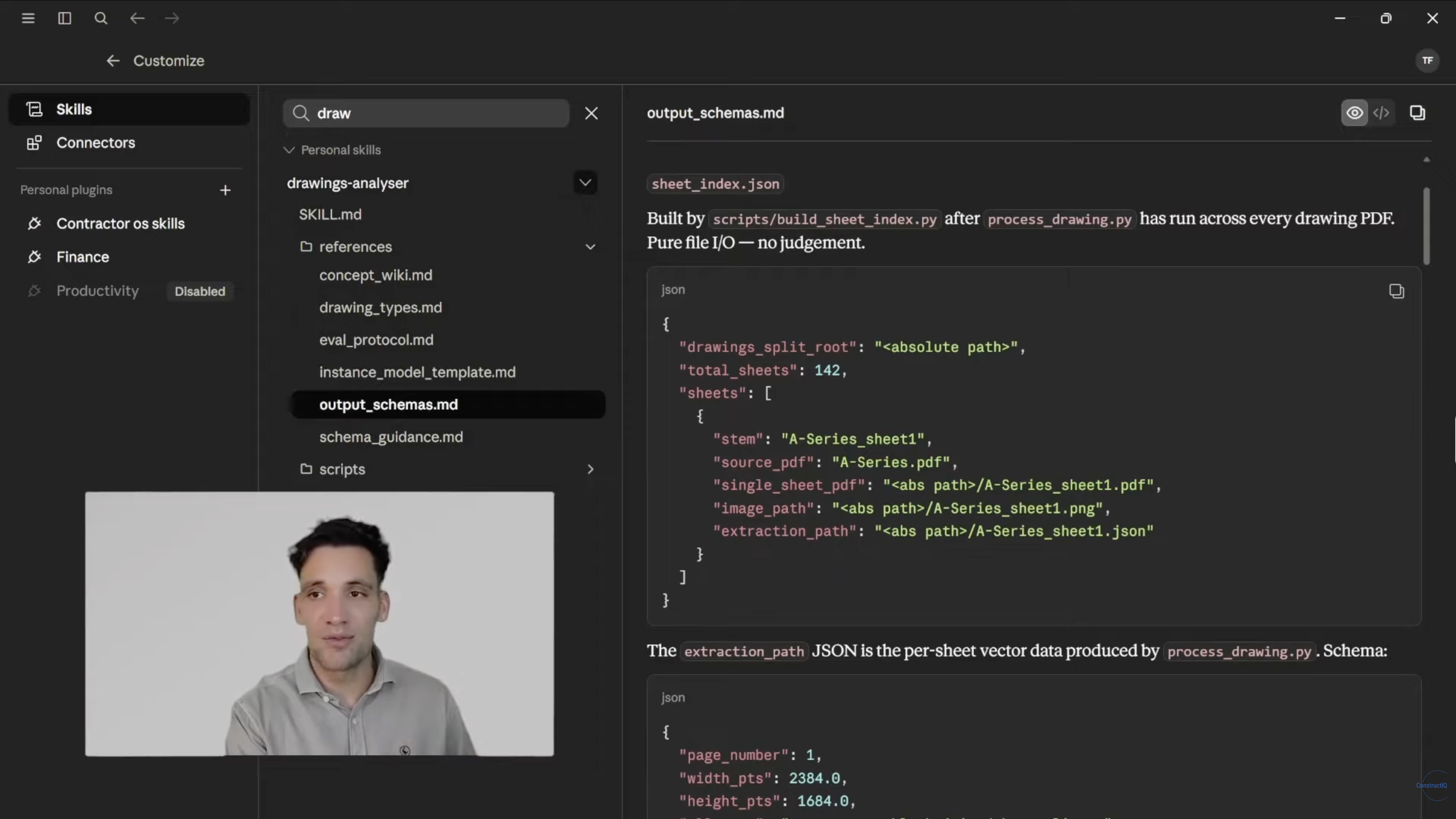
- Open the object database. This database groups information by construction object instead of sheet number. It can contain records for slabs, footings, pipe runs, cable runs, and other physical elements.
- Search for a known drawing tag. Find an item such as an F10 footing or warehouse slab. Its record can include dimensions, material details, and the source drawing. This brings together information that may appear on separate sheets.
- Check the reliability rating. The database records how Claude obtained each value. Schedule values and direct counts can receive higher confidence. Scaled measurements may receive medium confidence because they rely on the drawing scale.
- Open one project wiki topic. The wiki groups written information by subject, such as concrete, electrical work, or quality assurance. Check that the relevant notes and specifications appear under the correct topic.
Fix missing records, incorrect sources, or misplaced requirements before moving to the query stage. A clean database gives Claude a reliable starting point and makes later answers easier to trace.
Step 8: Query the Processed Drawings in the Correct Order
After Claude has processed the drawing set and you have checked the generated files, begin the query phase. Ask a clear question about the information you need.
For example, ask Claude Code:
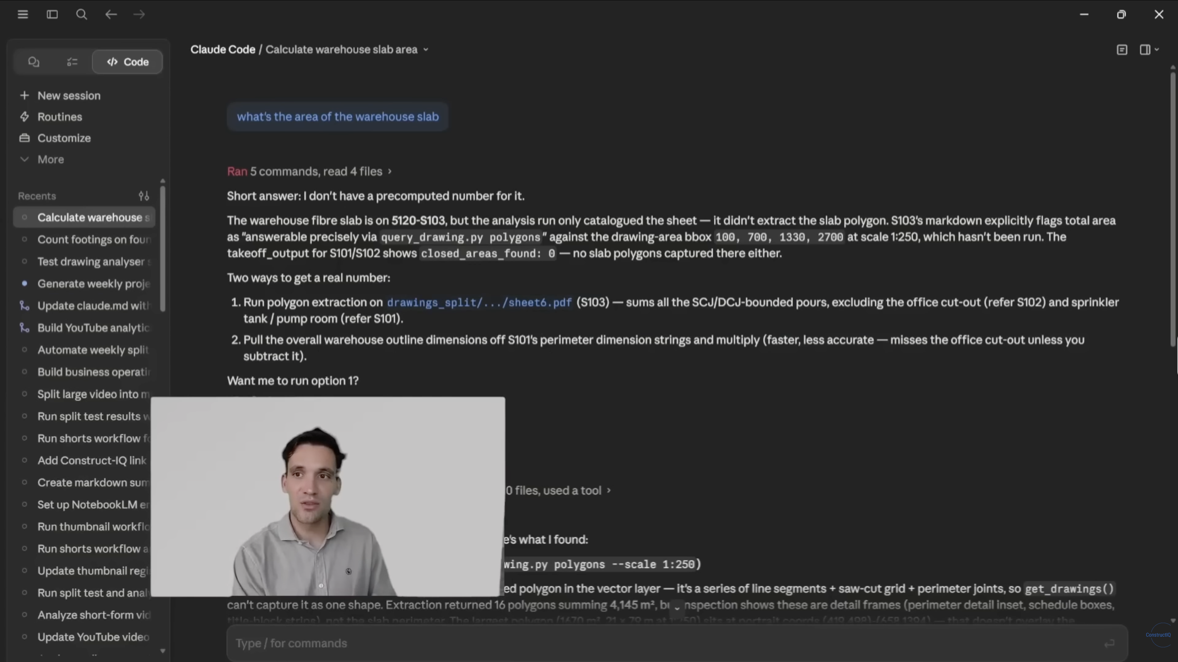
What is the area of the warehouse slab?
Claude should begin with drawings.md to understand the drawing package. It then uses the cross-reference indexes and structured database to identify the relevant sheet.
Once Claude finds the sheet, it reads the extracted text first. It can then inspect the rendered image and open the individual PDF when more detail is required.
For the warehouse slab query, Claude can extract the slab polygon from the drawing’s vector data. It can also calculate the area from the overall warehouse dimensions. Step 9 explains how to use both methods to check the result.
Written requirements follow a similar route through the project wiki. For example, ask:
What is the specification of concrete on the drawings?
Claude should locate the relevant concrete topic in the wiki. It can return to the source drawing when the extracted information does not provide enough detail.
Step 9: Request Sources and Cross-Check the Calculation
Review Claude’s answer before relying on the result. The response should show how the answer was produced and where the supporting information came from.
Check that the response includes:
- The result: The final count, measurement, quantity, or specification.
- The source: The drawings Claude used to produce the answer.
- The method: How Claude counted, measured, or extracted the information.
- The confidence: The reliability assigned to the result.
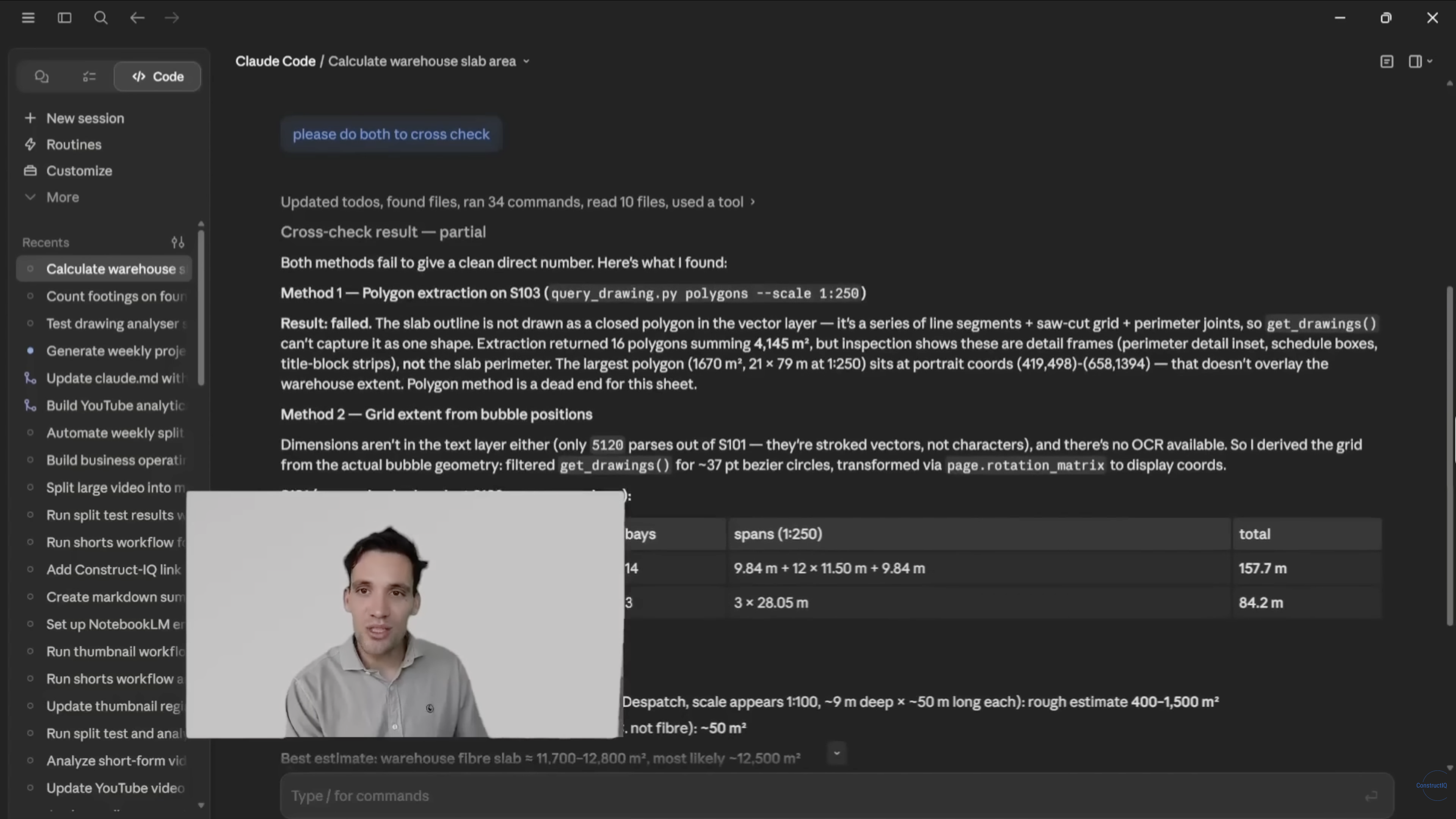
For quantities and measurements, use a second calculation method as a cross-check. In the warehouse slab example, Claude should identify two available methods. It should extract the slab polygon from the vector data or calculate the area from the overall warehouse dimensions.
For example, follow up with this prompt:
Run both to cross-check.
The polygon method provides a precise measurement from the drawing data. The overall dimensions provide an order-of-magnitude check. A large difference between the two results indicates that the measurement or selected drawing area needs further review.
Step 10: Verify the Result Against the Original Drawings
Complete a manual source check before using Claude’s answer. Open the drawings cited in the response and compare the result with the original information.
- Open the cited sheets. Check that Claude used the correct layout, section, detail, schedule, or notes page.
- Trace the supporting information. Confirm the dimensions, counts, specifications, and cross-references used in the answer. Follow any tags that lead to information on another sheet.
- Repeat the key measurement or count. Use the original PDF to check important results manually. A PDF measurement tool such as Bluebeam can help verify areas and dimensions.
Give extra attention to values marked with low confidence. The workflow is designed to return to the original drawing when the structured data does not provide enough detail.
Alternative Setup: Use Airtable as the Drawing Database
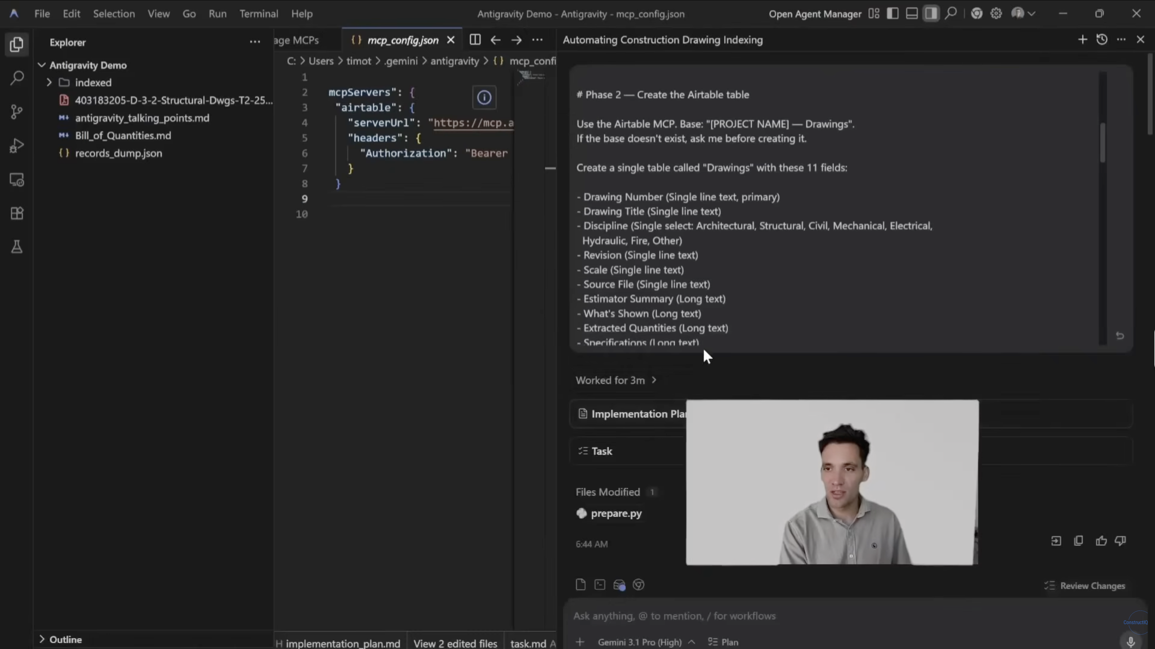
Airtable can store extracted drawing information in a searchable database. Claude can access the records through an MCP connection and retrieve the information needed for each query.
- Open Google Antigravity in the drawing folder. Select the local folder containing the merged PDF drawing set.
- Connect Airtable through MCP. Create an Airtable personal access token and add it to the MCP connection. Keep the token private and replace it if it becomes exposed.
- Process the drawing package. Instruct Antigravity to split the merged PDF, render each sheet as an image, and extract the available vector data.
- Write the extracted data to Airtable. The processing scripts add the drawing information to the database in a searchable text format.
- Connect Claude to Airtable. Claude can search the database and retrieve specific drawing records. Add instructions directing it to the original PDF when the database does not contain enough detail.
For example, ask Claude with this prompt:
Using my Airtable MCP connection, can you give me a summary of the warehouse drawings?
Change the question to suit the task. The same database can support searches for drawing contents, specifications, quantities, or the location of project information.
Alternative Setup: Use NotebookLM to Create Drawing Summaries
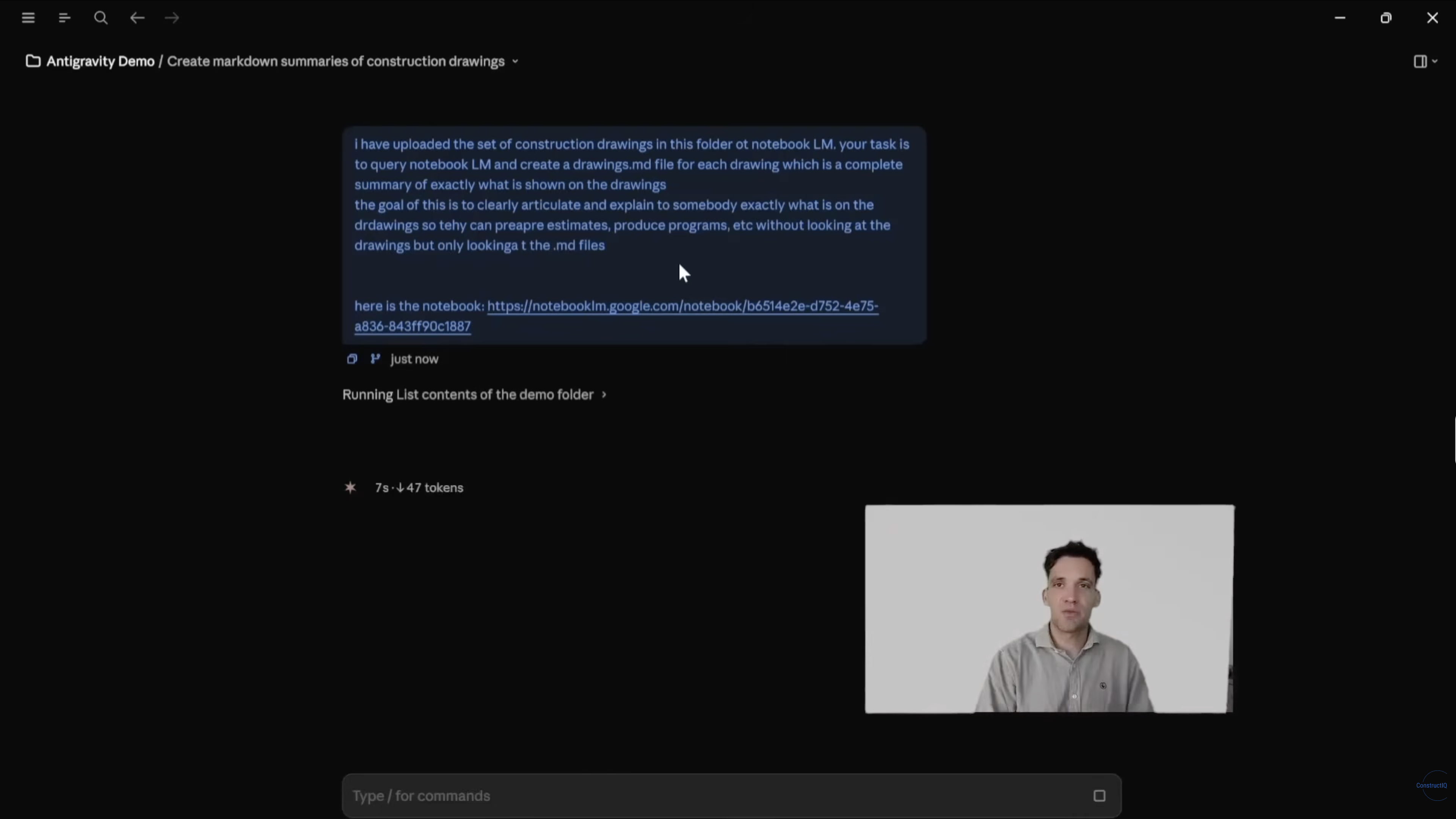
NotebookLM can process the drawing package and help Claude create a text summary for each sheet. Claude can then search the smaller Markdown files when answering questions about the drawings.
- Upload the drawing set to NotebookLM. Add the complete PDF package as a notebook source and wait for NotebookLM to process it.
- Connect NotebookLM to Claude Code. Open Claude Code in the local drawing folder and connect it to the notebook.
- Create a summary for each drawing. Ask Claude to query NotebookLM and generate a separate Markdown file for every sheet. Each summary can record the drawing contents, dimensions, notes, and material specifications.
- Save the summaries in the project folder. Claude can search these text files without loading the complete PDF for every query.
After uploading the drawing set to NotebookLM, open the project folder in the connected coding agent and try this prompt:
I have uploaded the construction drawing set from this folder to NotebookLM.
Query the NotebookLM notebook and create a separate Markdown file for each drawing. Each file should provide a complete summary of what appears on that drawing, including its contents, dimensions, specifications, schedules, notes, symbols, and cross-references where available.
The summaries should help someone understand the drawing when preparing an estimate, construction program, or related project task. Refer back to the original drawing whenever information is unclear or requires verification.
NotebookLM link: [insert notebook link]
Replace the bracketed text with the URL of the NotebookLM notebook. Review the generated summaries against the source drawings, then adjust the extraction instructions to capture the information needed for your tasks.
Make Construction Drawings Easier for AI to Read
Getting AI to read construction drawings comes down to preparation. Split and index the drawings so Claude can locate the right sheets before opening the source PDFs. Test the workflow on one familiar package, verify the answers, and save the analyzer once the results are reliable.
.avif)
Written by
Doug Vincent
Doug Vincent is the co-founder and CEO of Mastt, the AI capital-project management platform used by governments, Fortune 500 companies, and consultancies across APAC, North America, and MENA. Before founding Mastt in 2019, he spent a decade at RPS delivering more than $2 billion in capital works, including the $2.1B Defence Navy Infrastructure program, and holds a CPSPM certification with the AIPM. He contributes content and speaks on AI in capital project delivery at Mastt.


Contributions by
Timothy Fairley
Timothy Fairley is the Founder of ConstructIQ and a Chartered Professional Engineer and PMP with 9 years delivering construction projects across renewable energy, rail, and infrastructure. He trained over 50,000 construction professionals worldwide through ConstructIQ’s courses and YouTube channel on estimating, procurement, and contract management. Timothy contributes content on construction cost management and estimating at Mastt.
Construction Material List Template
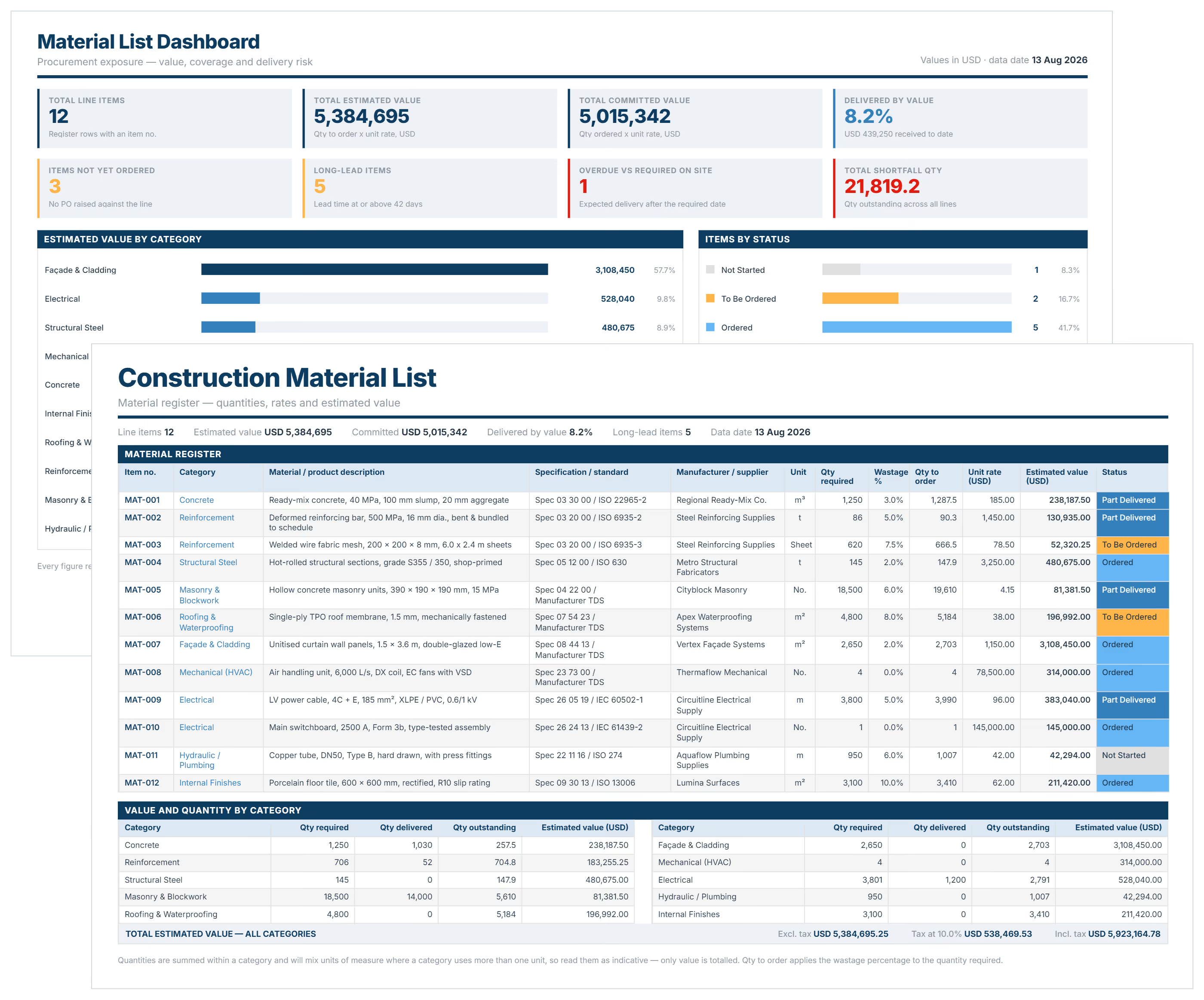
Use this construction material list template to organize quantities, costs, and suppliers for accurate procurement. Track materials from takeoff through delivery and prevent budget overruns with structured material documentation.

Walk Into Every Meeting With Confidence, Clarity, and Control
No one wants to look unprepared, blindsided, or uncertain in front of stakeholders — but that’s exactly what happens without Mastt.
Start for FreeTrusted by the bold, the brave, and the brilliant across governments, Fortune 500s, and the world’s best in delivering the future

